H-IIA & H-IIB
Production and Launch Operations
Production
Mitsubishi Heavy Industries is the primary contractor for the H-II series. The engines and vehicle stages are manufactured at Mitsubishi’s Nagoya plant and are shipped directly from Nagoya Bay to Tanegashima. The following major companies are involved in the H-II program.
Organization | Responsibility |
Mistubishi Heavy Industries | Systems integration |
Ishikawajima Harima Heavy Industries | LE-7A and LE-5B turbopumps |
Japan Aviation Electronics Industry | IMU |
Kawasaki Heavy Industries | Payload fairings, adapters |
Mitsubishi Precision Company | Avionics |
NEC Corporation | Avionics |
IHI Aerospace | SRB-A boosters |
ATK Thiokol | SSB motors |
Launch Operations–Tanegashima Space Center
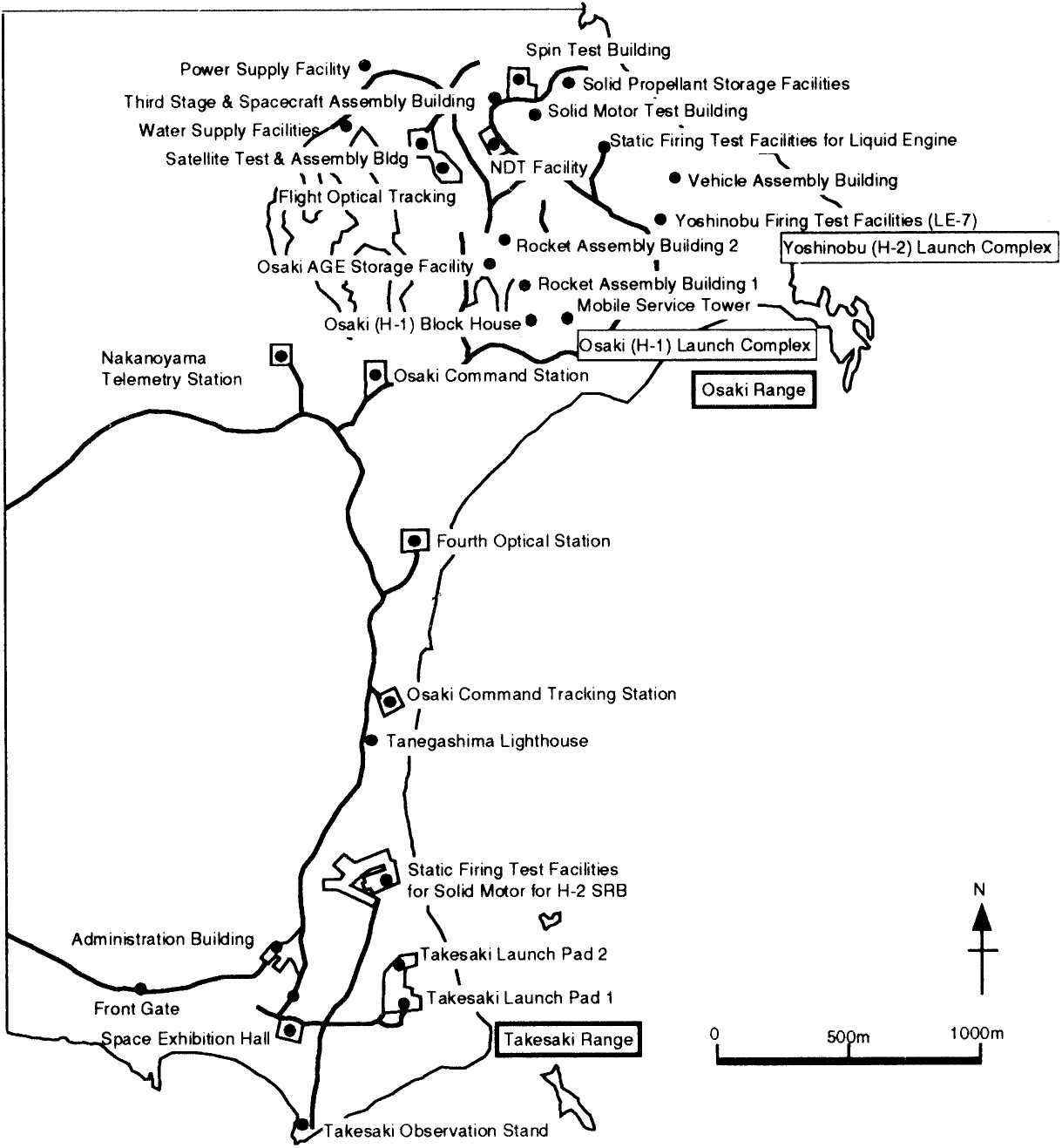
The Tanegashima Space Center is located on the southeastern coast of Tanegashima Island, Kagoshima Prefecture. Tanegashima Island, which is 58 km (36 mi) long with a population of about 40,000, is located 40 km (25 mi) off the southern coast of Kyushu, the southernmost of the four major islands in the Japanese chain. The facilities include the Takesaki Range for sounding rockets and the Osaki Range for space launch vehicles. The center also includes the Masuda Tracking and Data Acquisition Station, the Masuda, Uchugaoka, and Tanegashima radar stations, and three optical tracking stations, as well as test firing facilities for solid and liquid engines. The center occupies approximately 8.6 km2 (3.3 mi2) of land and is the largest launch site in Japan. The major tasks of the center are to check, assemble, and launch rockets, and to perform tracking and control after launch. The center is Japan’s primary site for launching applications satellites and test firing solid rocket motors and liquid rocket engines. As a result of objections from fishing unions to the hazards associated with the launches over their fishing grounds, launch windows are restricted to two launch periods each year. In the past these periods lasted from 15 January to 28 February and 1 August to 15 September. However, JAXA has negotiated an increase in the duration of the available launch periods, to support higher flight rates. The new periods cover 1 January through 28 February, and 22 July through 30 September. In addition, two 60-day periods encompassing June to July and November to December are available as launch windows for high-priority launches such as planetary or international missions.
Launch Site

Launch Facilities
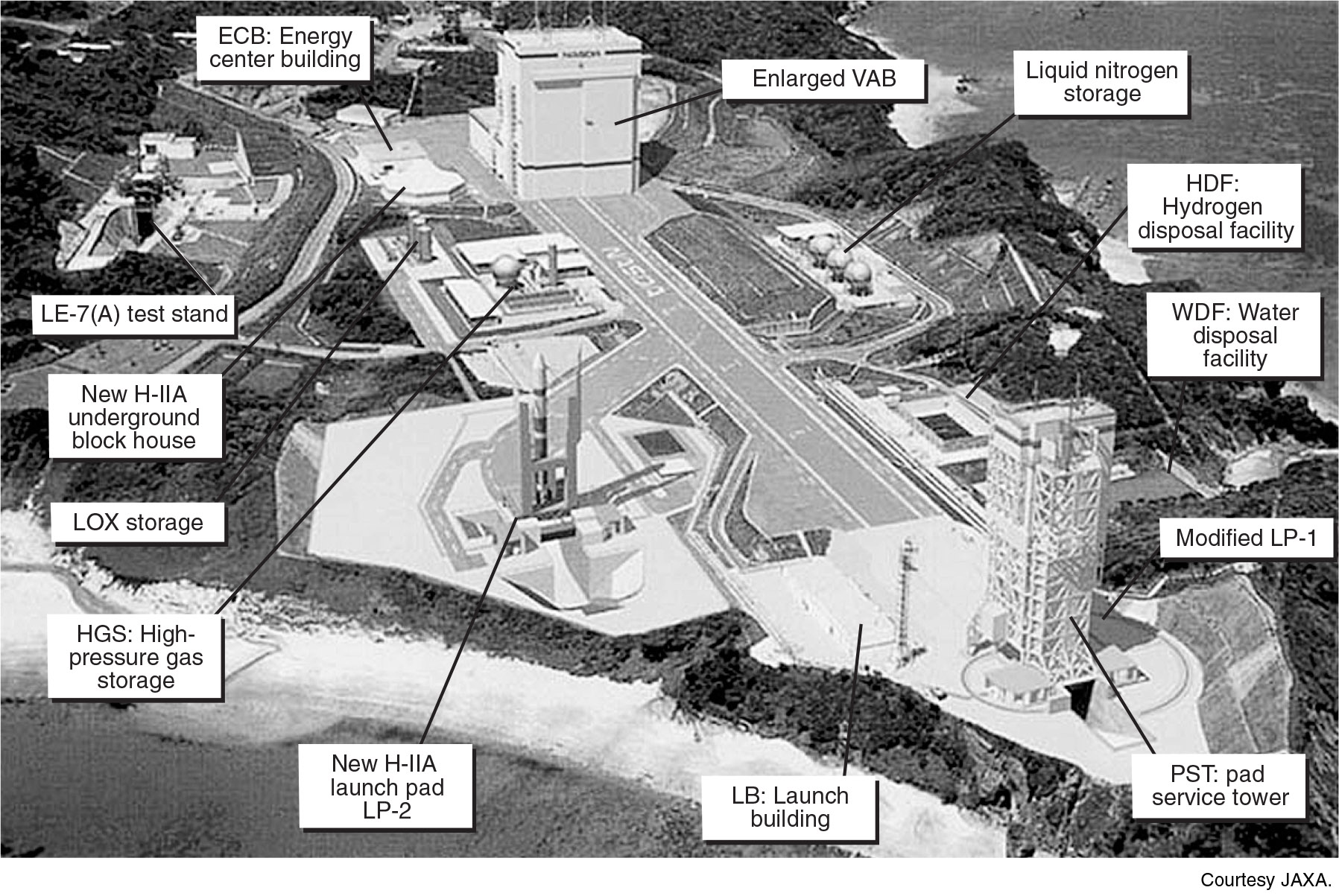
Construction of the Yoshinobu Launch Complex for launching H-II rockets at the Osaki Range was begun in 1985. The major facilities in the complex are the Vehicle Assembly Building (VAB), the mobile launcher (ML), two launch pads, the blockhouse, and propellants and high-pressure gas storage. Adjacent to those facilities, a test stand was constructed to conduct firing tests of the LE-7 and LE-7A. An x-ray computer tomography facility is available for nondestructive inspections of SRBs. Launch operations are controlled from within the octagonal Yoshinobu blockhouse and directed from the Takesaki Range Control Center.
The VAB is a 66-m (215-ft) high structure with two bays for vertical stacking of launch vehicles. The second bay was added for the H-IIA program to support the planned increase in flight rates. While the H-II program performed only vehicle integration and basic checkout in the VAB with most tests performed after rollout to the launch pad, the H-IIA is designed to perform all tests in the VAB and is rolled out to the pad less than 24 h before launch. The launch vehicle is assembled on the deck of one of two MLs. Major umbilicals to the vehicle and payload are routed through service masts mounted on the ML. When vehicle integration and testing are complete and the spacecraft has been mated to the launch vehicle, the booster is carried by the ML along a 500-m (1600-ft) route to the launch pad.
There are two launch pads at the Yoshinobu Launch Complex. Launch Pad 1, built for the H-II program, includes a large Pad Service Tower (PST). The PST stands 75 m (245 ft) high. It consists of a fixed service structure and two rotating service structures that can open to both sides before launch. The fixed service structure includes work platforms at different levels to access the vehicle, and a 20-ton bridge crane to lift the encapsulated fairing and payload into place. Launch Pad 2, built for the H-IIA, is a simple “clean pad” design with no access tower, reflecting the simplified operations sequence for the H-IIA. All interfaces to the launch vehicle are provided by the umbilical masts on the ML.
facilitiesontanegashimaisland.jpg?sfvrsn=3e0ad2a5_0)
Location of JAXA (NASDA) Facilities on Tanegashima Island


H-II Yoshinobu Launch Site Layout

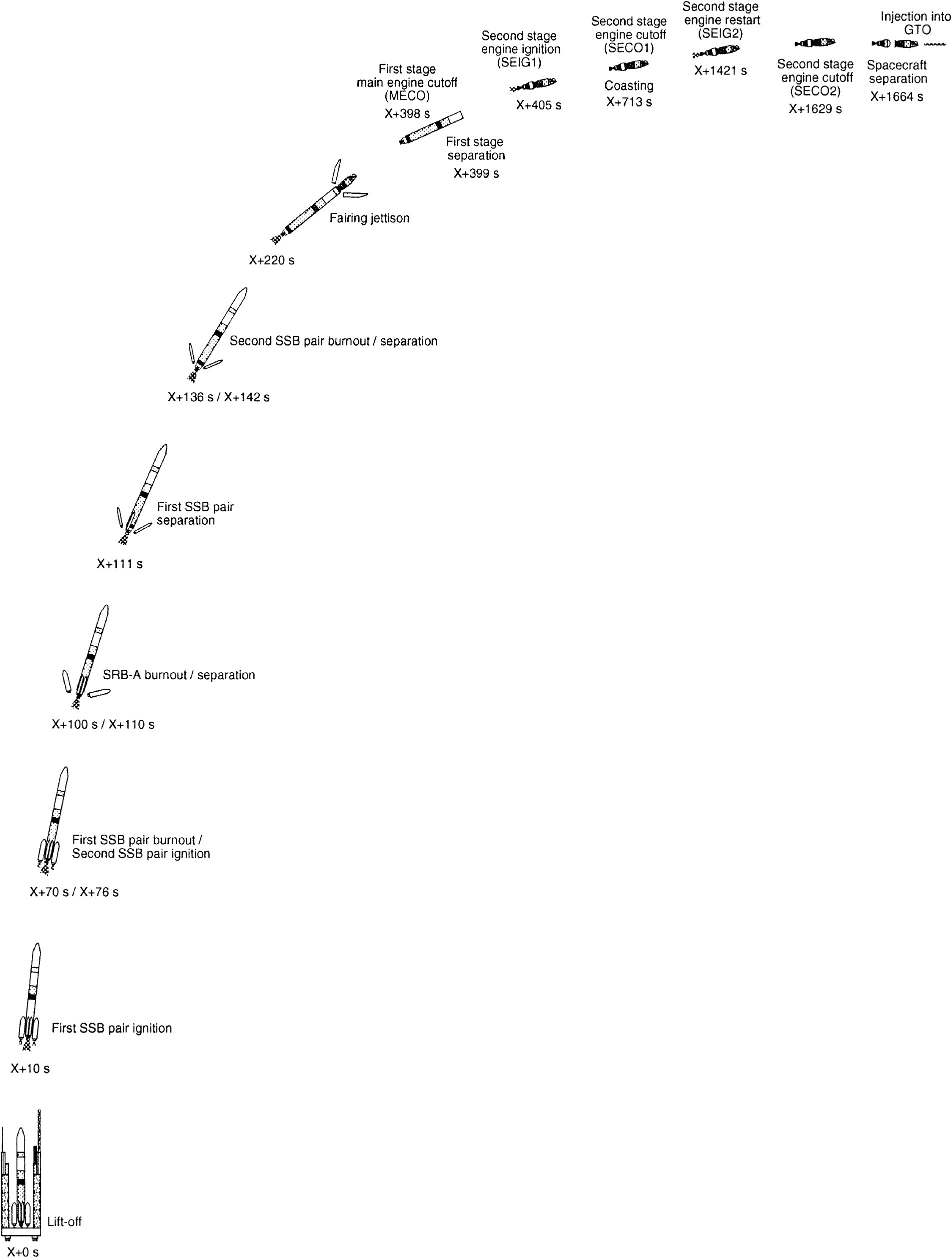
H-IIA204 GTO Flight Sequence
H-IIA Flight Sequence | H2A202 | H2A2024 |
LE-7AIgnition | –6 | –6 |
SRB-AIgnition | –0.6 | –0.6 |
Liftoff | 0 | 0 |
First SSB Pair Ignition | — | 10 |
SRB-A Burnout | 100 | 100 |
SRB-A Separation | 110 | 110 |
First SSB Pair Burnout | — | 70 |
Second SSB Pair Ignition | — | 76 |
First SSB Pair Separation | — | 111 |
Second SSB Pair Burnout | — | 136 |
Second SSB Pair Separation | — | 142 |
Fairing Jettison | 264 | 220 |
First-Stage Main Engine Cutoff | 389 | 389 |
First-Stage Separation | 399 | 399 |
Second-Stage First Ignition | 405 | 405 |
Second-Stage First Cutoff | 732 | 713 |
Second-Stage Second Ignition | 1466 | 1421 |
Second-Stage Second Cutoff | 1651 | 1629 |
Payload Separation | 1687 | 1664 |