Falcon
Payload Accommodations
Payload Compartment
Maximum Payload Diameter 4600 mm (15.1 ft)
Maximum Cylinder Length 1100 mm (36.1 ft)
Maximum Cone Length 2794 mm (60 in.)
Payload Adapter Interface Diameter 937-mm or 1194-mm (36.89 in. or 47.01 in.)
Payload Integration
Nominal Mission Schedule Begins T–7 days
Environment
Maximum Axial Load 6.4 g
Maximum Lateral Load 2 g
Maximum Acoustic Level 122 dB
Overall Sound Pressure Level 131 dB
Maximum Flight Shock 1400 ft
Maximum Dynamic Pressure on Fairing 33.5 kPa (700 lbf/ft2)
Maximum Aeroheating Rate at Fairing Separation 1135 W/m2 (0.1 BTU/ft2/s)
Cleanliness Level in Fairing 10,000 (Class 7)
Payload Delivery
Standard Orbit Injection Accuracy (3 sigma) ±10 km (18 nmi) at perigee, ±20 km (36 nmi) at apogee
Attitude Accuracy (3 sigma) 0.5°
Nominal Payload Separation Rate 0.1–0.9 m/s (1–3 ft/s)
Nominal Payload Tip Off Rate < 1 deg/s
Deployment Rotation Rate Available 1 rpm
Loiter Duration in Orbit 1 h
Maneuvers (Thermal/Collision Avoidance) Yes
Multiple/Auxiliary Payloads
Multiple or Comanifest Falcon will accommodate comanifest payloads
Auxiliary Payloads Falcon will accommodate secondary and piggyback payloads
Flight Attitude
Falcon 9 and Falcon Heavy can provide payload pointing and roll control during long-duration coast phases for sun avoidance and thermal control. If requested, the Falcon second stage will point the X-axis of the launch vehicle to a customer-specified attitude and perform a passive thermal control roll of up to ±1.5 deg/sec around the launch vehicle X-axis, held to a local vertical/local horizontal (LVLH) roll attitude accuracy of ±5 deg.
Separation Attitude and Accuracy
Falcon launch vehicles offer 3-axis attitude control or spin-stabilized separation as a standard service. For inertial separation, the vehicle will point the second stage and payload to the desired LVLH attitude and minimize attitude rates. For spin-stabilized separation, the Falcon launch vehicle will point the second stage and payload to the desired LVLH attitude and initiate a spin about the launch vehicle X-axis at a customer-specified rate dependent upon payload mass properties. Standard pre-separation attitude and rate accuracies are developed as a mission-specific standard service. More information about separation attitude and rate accuracy is available from SpaceX upon request.
Multiple Payloads
Falcon 9 and Falcon Heavy can launch multiple satellites on a single mission, with the customer responsible for the integration of the multiple payloads. As a liquid-propellant launch vehicle with restart capability, Falcon launch vehicles also provide the flexibility to deploy each satellite into a different orbit, performance allowing.
Falcon launch vehicles can accommodate a broad range of dispenser systems including multi-payload systems, dual-payload attach fittings and mission-unique adapters. SpaceX can develop and provide such adapters and dispensers if desired, as a nonstandard service, or can integrate third-party systems. Contact SpaceX with your mission-unique requirements.
Secondary Payloads
SpaceX typically reserves the right to manifest secondary payloads aboard Falcon missions on a non-interference basis. Secondary payloads may be manifested on a variety of secondary payload adapters including an Evolved Expendable Launch Vehicle (EELV) Secondary Payload Adapter (ESPA) ring, a SpaceX-developed Surfboard, or other mission-unique secondary deployment structures. Contact SpaceX or a secondary payload broker for information regarding flight opportunities, interface requirements and pricing for secondary payloads.
Environments
Falcon 9 and Falcon Heavy have been designed to provide as benign a payload environment as possible, via the use of all-liquid propulsion, a single staging event, deeply throttleable engines and pneumatic separation systems. The environments presented below reflect typical mission levels for Falcon 9 and Falcon Heavy; mission-specific analyses will be performed and documented in an interface control document for each contracted mission
Transportation Environments
SpaceX recommends using the quasi-static limit load factors provided by NASA-HDBK-7005 (Table 4-1 below). SpaceX has quantified the maximum predicted environments experienced by the payload during transportation. Transportation will be accomplished by two wheeled vehicles: a payload transporter from the payload processing facility to the hangar, and the launch vehicle transporter-erector from the hangar to the launch pad. It is expected that transportation environments will be enveloped by the flight environments shown below.
Table 4-1: Recommended quasi-static load factors for transportation
Transportation Method | Longitudinal Load (g) | Lateral Load (g) | Vertical Load (g) |
Slow-moving dolly (expected ground transport loads) | ± 1.0 | ± 0.75 | ± 2.0 |
4.2 TEMPERATURE, HUMIDITY AND CLEANLINESS
The standard service temperature, humidity and cleanliness environments during various processing phases are provided in Table 4-2. SpaceX can accommodate environments outside the standard service, e.g. ISO Class 7 (Class 10,000) cleanroom cleanliness. Please contact SpaceX for details.
Conditioned air will be disconnected for a short duration during rollout to the pad. Spacecraft environmental temperatures will be maintained above the dew point of the supply air at all times. A nitrogen purge is available as a nonstandard service. The payload attach fitting (PAF) and fairing surface are cleaned to Visibly Clean-Highly Sensitive, achieving a residue level between A/5 and A/2 and particulate between 300-500 micron, per IEST-STD-CC1246D.
Phase | Control System | Approx. Duration | Temp. °C (°F) | Humidity | Cleanliness (class) | Flow Rate(cfm) |
Spacecraft processing | Payload processing facility heating, ventilation and air conditioning | 3 weeks | 21 ± 3 (70 ± 5) | CCAFS/KSC: 45% ± 15% VAFB: | 100,000 | N/A |
Propellant conditioning | Facility heating, ventilation and air conditioning (HVAC) | 3 days | 21 ± 3 (70 ± 5) | CCAFS/KSC: 45% ± 15% VAFB: | 100,000 | N/A |
Spacecraft propellant loading | Facility heating, ventilation and air conditioning | Mission- Unique | 21 ± 3 (70 ± 5) | CCAFS/KSC: 45% ± 15% VAFB: | 100,000 | N/A |
Transport to hangar (CCAFS/KSC | Transport trailer unit | <6 hrs | 21 ± 3 (70 ± 5) | 0%-60% | 10,000 | 1,000 |
Phase | Control System | Approx. Duration | Temp. °C (°F) | Humidity | Cleanliness (class) | Flow |
Encapsulated in hangar | Ducted supply from hangar facility HVAC | 1 week | 21 ± 3 (70 ± 5) | CCAFS/KSC: 45% ± 15% VAFB: 50% ± 15% | 10,000 (Class 7) (supply air cleanliness) | 1,000 |
Encapsulated | None | 30-60 min | N/A | N/A | 10,000 (Class 7) | N/A |
Encapsulated on pad (vertical or horizontal) | Pad air conditioning | <1 day | VAFB: Selectable 15 to 35 (59 to 95) | 0% to 65% | 10,000 (Class 7) (supply air cleanliness) | 1,500 |
4.3 FLIGHT ENVIRONMENTS
The maximum predicted environments the payload will experience from liftoff through separation are described in the sections below. Falcon vehicles may be able to accommodate payloads with characteristics
outside the limitations indicated in these sections and may also be able to provide environments lower than those indicated in these sections. Please contact SpaceX with your mission-unique requirements.
4.3.1 LOADS
During flight, the payload will experience a range of axial and lateral accelerations. Axial acceleration is driven by vehicle thrust and drag profiles; lateral acceleration is primarily driven by wind gusts, engine gimbal
maneuvers, first-stage engine shutdown and other short-duration events. Both the first- and second-stage engines may be throttled to help maintain launch vehicle and payload steady state acceleration limits.
For “standard” payloads with mass of more than 4,000 lb (1,810 kg), Falcon 9 and Falcon Heavy payload design load factors are shown using the envelope in Figure 4-1. For “light” payloads with mass of less than 4,000 lb (1,810 kg), Falcon 9 load factor is provided in Figure 4-2. For Falcon Heavy “light” payloads, please contact SpaceX for more details.
The load factors provided below are intended for a single payload mission; multi-payload missions should coordinate directly with SpaceX. A positive axial value indicates a compressive net-center-of-gravity acceleration, while a negative value indicates tension. Actual payload loads, accelerations and deflections are a function of both the launch vehicle and payload structural dynamic properties and can be accurately determined via a coupled loads analysis.
Secondary structure designs should consider maintaining a minimum resonant frequency above 35Hz to avoid interaction with launch vehicle dynamics.
4.3.1.1 FALCON 9 AND FALCON HEAVY LOADS – STANDARD PAYLOAD MASS
The Falcon 9 and Falcon Heavy design load factors provided below are for typical spacecraft above 4,000 lb. Please consult with SpaceX for applicability based
on spacecraft modal frequencies and CG height.
Figure 4-1: Falcon 9 and Falcon Heavy payload design load factors for “standard” mass (over 4,000 lb)
4.3.1.2 FALCON 9 LOADS – LIGHT PAYLOAD MASS
Figure 4-2 shows the Falcon 9 design load factors for lighter payloads (less than 4,000 lb). However, for ultra-light payloads (~2,000 lb or less), coordination with SpaceX
mission management is required, since these load factors may not be adequate to design the payload. Actual spacecraft loads, accelerations and deflections are a function of both the launch vehicle and payload structural dynamic properties and can
only be accurately determined via a coupled loads analysis.

Figure 4-2: Falcon 9 payload design load factors, light mass (under 4,000 lb)
4.3.1.3 FALCON HEAVY LOADS – LIGHT PAYLOAD MASS
Please contact SpaceX for more information.
4.3.2 SINE VIBRATION
Maximum predicted sinusoidal vibration environments represent the levels at the top of the payload attach fitting for Q=20 through Q=50, and envelope all stages of flight. Maximum predicted sinusoidal vibration
environments for Falcon 9 and Falcon Heavy are shown in Figure 4-3 and Figure 4-4. These environments represent the vibration levels at the top of the payload attach fitting for Q=20 through Q=50,
and envelope all stages of flight. Since SpaceX accommodates a variety of payloads, results of coupled loads analysis will be used to modify these levels, if necessary, to reflect the levels at the payload interface.

Figure 4-3: Maximum axial equivalent sine environment for Falcon 9 and Falcon Heavy

Figure 4-4: Maximum lateral equivalent sine environment for Falcon 9 and Falcon Heavy
4.3.3 ACOUSTIC
During flight, the payload will be subjected to a varying acoustic environment. Levels are highest near liftoff and during transonic flight, due to aerodynamic excitation. The acoustic environment, defined as
the spatial average and derived at a P95/50 level, is shown by both full and third-octave curves.
4.3.3.1 FALCON 9 ACOUSTICS
Figure 4-5 and Table 4-3 provide the Falcon 9 third-octave maximum predicted acoustic environment for typical payloads, while Figure 4-6 and Table 4-4 provide the full-octave maximum predicted acoustic
environment. Levels are shown for both Cape Canaveral (SLC-40 and LC-39A) and Vandenberg (SLC-4E) launch sites respectively. Predicted acoustic levels for a specific mission will depend on the payload’s size and volume with smaller payloads
generally having lower acoustic levels. Margin for qualification testing or for payloads larger than 60% volume fill is not included in the curves below.
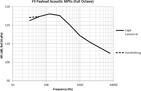
Figure 4-5: Falcon 9 maximum predicted acoustic environment (P95/50), 60% fill-factor, 131.3 dB OASPL (Cape Canaveral) and 131.4 dB OASPL (Vandenberg) in third octave
Table 4-3: Falcon 9 maximum predicted acoustic environment (P95/50), 60% fill-factor
Frequency (Hz) | Cape Canaveral Acoustic Limit Levels (P95/50), 60% Fill-Factor (Third-Octave) | Vandenberg Acoustic Limit Levels (P95/50), 60% Fill-Factor (Third-Octave) | |
31.5 | 118 | 119.75 | |
40 | 119.5 | 120 | |
50 | 120 | 120 | |
63 | 120 | 120 | |
80 | 119.8 | 119.8 | |
100 | 120.5 | 120.5 | |
125 | 121.5 | 121.5 | |
160 | 122 | 122 | |
200 | 121.5 | 121.5 | |
250 | 120.5 | 120.5 | |
315 | 119 | 119 | |
400 | 117 | 117 | |
500 | 115 | 115 | |
630 | 113 | 113 | |
800 | 111 | 111 | |
1000 | 109.5 | 109.5 | |
1250 | 108 | 108 | |
1600 | 107 | 107 | |
2000 | 106 | 106 | |
2500 | 105 | 105 | |
3150 | 104 | 104 | |
4000 | 103 | 103 | |
5000 | 102 | 102 | |
6300 | 101 | 101 | |
8000 | 100 | 100 | |
10000 | 99 | 99 | |
OASPL (dB) | 131.3 | 131.4 | |

Figure 4-6: Falcon 9 maximum predicted acoustic environment (P95/50), 60% fill-factor, 131.4 dB OASPL (Cape Canaveral) and 131.6 OASPL (Vandenberg) in full octave
Table 4-4: Falcon 9 maximum predicted acoustic environment (P95/50), 60% fill-factor
Frequency (Hz) | Cape Canaveral Acoustic Limit Levels (P95/50), 60% Fill-Factor, (Full Octave) | Vandenberg Acoustic Limit Levels (P95/50), 60% Fill- Factor, (Full Octave) |
31.5 | 122.4 | 124.1 |
63 | 124.7 | 124.7 |
125 | 126.1 | 126.1 |
250 | 125.2 | 125.2 |
500 | 120.1 | 120.1 |
1000 | 114.4 | 114.4 |
2000 | 110.8 | 110.8 |
4000 | 107.8 | 107.8 |
8000 | 104.8 | 104.8 |
OASPL (dB) | 131.4 | 131.6 |
4.3.3.2
FALCON HEAVY ACOUSTICS
Figure 4-7 and Table 4-5 provide the Falcon Heavy third-octave maximum predicted acoustic environment for typical payloads, while Figure 4-8 and Table 4-6 provide the full-octave maximum predicted acoustic environment.
These levels are applicable to future contracts from Cape Canaveral (LC-39A). Predicted acoustic levels for a specific mission will depend on the payload’s size and volume with smaller payloads generally having lower acoustic levels. Margin
for qualification testing or for payloads larger than 60% volume fill is not included in the curves below.
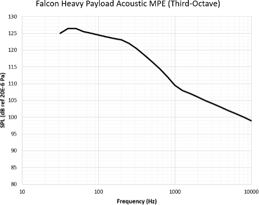
Figure 4-7: Falcon Heavy maximum predicted acoustic environment (P95/50), 60% fill-factor, 135.2 dB OASPL (third octave)
Table 4-5: Falcon Heavy maximum predicted acoustic environment (P95/50),
60% fill-factor, 135.2 dB OASPL (third octave)
Frequency (Hz) | Acoustic Limit Levels (P95/50), 60% Fill-Factor (Third-Octave) |
31.5 | 125 |
40 | 126.5 |
50 | 126.5 |
63 | 125.5 |
80 | 125 |
100 | 124.5 |
125 | 124 |
160 | 123.5 |
200 | 123 |
250 | 122 |
315 | 120.5 |
400 | 118.5 |
500 | 116.5 |
630 | 114.5 |
800 | 112 |
1000 | 109.5 |
1250 | 108 |
1600 | 107 |
2000 | 106 |
2500 | 105 |
3150 | 104 |
4000 | 103 |
5000 | 102 |
6300 | 101 |
8000 | 100 |
10000 | 99 |
OASPL (dB) | 135.2 |
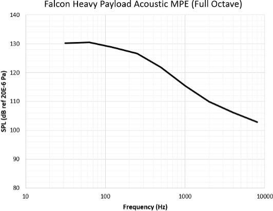
Figure 4-8: Falcon Heavy maximum predicted acoustic environment (P95/50), 60% fill-factor, 135.6 dB OASPL (full octave)
Table 4-6: Falcon Heavy maximum predicted acoustic environment (P95/50),
60% fill-factor, 135.6 dB OASPL (full octave)
Frequency | Acoustic Limit Levels (P95/50), 60% Fill-Factor (Full Octave) |
31.5 | 130.3 |
63 | 130.5 |
125 | 128.8 |
250 | 126.7 |
500 | 121.6 |
1000 | 114.9 |
2000 | 110.8 |
4000 | 107.8 |
8000 | 104.8 |
OASPL (dB) | 135.6 |
4.3.4
SHOCK
Five events during flight result in loads that are characterized as shock loads:
- Release of the launch vehicle hold-down at liftoff.
- Booster separation (Falcon Heavy only).
- Stage separation.
- Fairing deployment.
- Spacecraft separation.
Of these events, the first three are negligible for the payload relative to fairing deployment and spacecraft separation because of the large distance and number of joints over which the shocks will travel and dissipate. The maximum shock environment predicted at the 1575-mm interface for fairing deployment is enveloped by the shock environment from typical spacecraft separation. Consequently, the shock environment is typically a function of the spacecraft adapter and separation system selected for the mission. Actual shock environments experienced by the payload at the top of the mission-unique payload adapter will be determined following selection of a specific payload adapter and separation system. Table 4-7 shows typical payload adapter-induced shock at the spacecraft separation plane for 937-mm or 1194- mm (36.89 in. or 47.01 in.) clampband separation systems, derived at a P95/50 statistical level. Please note the actual flight shock levels produced by the payload adapter will be mission-unique.
Table 4-7: Payload adapter-induced shock at the spacecraft separation plane (P95/50)
Frequency (Hz) | SRS (g) |
100 | 30 |
1000 | 1,000 |
10000 | 1,000 |
4.3.5 RANDOM VIBRATION
The maximum predicted random vibration environment at the top of the Payload Attach Fitting (PAF) can be seen in Figure 4-9 and Table 4-8. This environment is derived from flight data measured at the
top of the PAF and does not account for any additional attenuation as the vibration traverses the mission specific payload adapter or spacecraft interface. The smoothline is an envelope of all flight events (liftoff, Stage 1 ascent, and S2 burns)
and is derived at a P95/50 statistical level.
The random vibration environment is derived from the maximum response due to multiple forcing functions. These forcing functions can be broken into three frequency bins as shown in Figure 4-10 and listed below:
Low Frequency (0 - 100Hz)
a. Excitations driven by global vehicle motion and modes
b. CLA and sine vibration envelope this region
2. Mid Frequency (100Hz – 600Hz)
a. Excitation due to aeroacoustics
b. Acoustic
excitation and aero buffet are primary drivers in this region
3. High Frequency (600Hz – 2000Hz)
a. Excitation due to structure borne vibration
b. Merlin Vacuum (MVac) forcing functions
Spacecraft complying with standard component level qualification practices such as GEVs or SMC-S-016 are generally covered for this environment. Spacecraft with sensitive components that are not screened to vibration levels above the Falcon MPE can assess if acoustic testing envelopes the random vibration environment. One approach to determine this is to measure acceleration responses near components during acoustic testing. Components closer to the spacecraft separation plane are more likely to be driven by random vibration as opposed to acoustics than those further away. Spacecraft components with high surface area to mass ratios such as photovoltaic arrays generally see higher excitations from acoustic environments than from random vibration. However, these criteria are subjective and engineering best judgement should be used.

Figure 4-9: Falcon 9/Heavy random vibration maximum predicted environment (P95/50) at top of PAF [5.13 GRMS]
Table 4-8: Falcon 9/Heavy random vibration maximum predicted environment
(P95/50) at top of PAF [5.13 GRMS]
| Frequency | Falcon 9/Heavy Payload Vibration MPE, (P95/50) 5.13 GRMS |
| 20 | 0.0044 |
| 100 | 0.0044 |
| 300 | 0.01 |
| 700 | 0.01 |
| 800 | 0.03 |
| 925 | 0.03 |
| 2000 | 0.00644 |
| GRMS | 5.13 |

Figure 4-10: Falcon 9/Heavy frequency bin breakdown
4.3.5.1 RANDOM VIBRATION ATTENUATION
Spacecraft with sensitive components not screened with standard level qualifications (GEVS or SMC-S-016) may require additional relief from random vibration. SpaceX offers random vibration attenuation
as a non-standard service. For programmatic information, please reach out to SpaceX directly.
4.3.6 ELECTROMAGNETIC
4.3.6.1 RF SYSTEM CHARACTERISTICS
Falcon launch vehicles include several radio frequency (RF) systems, which are summarized in Table 4-9 for Falcon 9 and Table 4-10 for Falcon Heavy.
Table 4-9: Falcon 9 RF systems characteristics
Part Description | TX/RX(transmitter/ receiver) | Frequency (MHz) | 99% Bandwidth (MHz) | Modulation |
S1TX1 Telemetry Transmitter | TX | 2247.5 | 4.84 | PCM/FM |
S1TX2 Telemetry Transmitter | 2255.5 | |||
S2TX1 Telemetry Transmitter | 2232.5 | 4.14 | ||
S2TX2 Telemetry Transmitter | 2272.5 | |||
GPS Receiver | RX | 1575.42 | 20 | BPSK DSSS |
Iridium/GPS Tracker | TX | 1610 - 1626.5 | 0.042 | BPSK/QPSK |
Iridium/GPS Tracker | RX | 1610 - 1626.5 | 0.042 | QPSK |
Iridium/GPS Tracker | RX | 1575.42 | 20 | BPSK DSSS |
S-Band BPSK Receiver | RX | 2090 - 2093 | 1 | BPSK |
Radar Altimeter | TX | 4235-4275 | 40 | FMCW |
Radar Altimeter | TX | 4325-4365 | 40 | FMCW |
Radar Altimeter | TX | 4250-4350 | 100 | FMCW |
Radar Altimeter | RX | 4235-4275 | 40 | FMCW |
Radar Altimeter | RX | 4325-4365 | 40 | FMCW |
Radar Altimeter | RX | 4250-4350 | 40 | FMCW |
Table 4-10: Falcon Heavy RF systems characteristics
Part Description | TX/RX (transmitter/receiver) | Frequency (MHz) | 99% Bandwidth | Modulation | ||||||
S1TX1 Telemetry Transmitter | TX | 2247.5 | 4.84 | PCM/FM | ||||||
S1TX2 Telemetry Transmitter | 2255.5 | |||||||||
S2TX1 Telemetry Transmitter | 2232.5 | 4.14 | ||||||||
S2TX2 Telemetry Transmitter | 2272.5 | |||||||||
SB1TX Telemetry Transmitter | 2370.5 | 4.88 | SOQPSK | |||||||
SB2TX Telemetry Transmitter | 2382.5 | |||||||||
GPS Receiver | RX | 1575.42 | 20 | BPSK DSSS | ||||||
Iridium/GPS Tracker | TX | 1610 - 1626.5 | 0.042 | BPSK/QPSK | ||||||
Iridium/GPS Tracker | RX | 1610 - 1626.5 | 0.042 | QPSK | ||||||
Iridium/GPS Tracker | RX | 1575.42 | 20 | BPSK DSSS | ||||||
S-Band BPSK Receiver | RX | 2090 - 2093 | 1 | BPSK | ||||||
Radar Altimeter | TX | 4235-4275 | 40 | FMCW | ||||||
Radar Altimeter | TX | 4325-4365 | 40 | FMCW | ||||||
Radar Altimeter | TX | 4212.5-4252.5 | 40 | FMCW | ||||||
Radar Altimeter | TX | 4302.5-4342.5 | 40 | FMCW | ||||||
Radar Altimeter | TX | 4257.5-4297.5 | 40 | FMCW | ||||||
Radar Altimeter | TX | 4347.5-4387.5 | 40 | FMCW | ||||||
Radar Altimeter | RX | 4235-4275 | 40 | FMCW | ||||||
Radar Altimeter | RX | 4325-4365 | 40 | FMCW | ||||||
Radar Altimeter | RX | 4212.5-4252.5 | 40 | FMCW | ||||||
Radar Altimeter | RX | 4302.5-4342.5 | 40 | FMCW | ||||||
Radar Altimeter | RX | 4257.5-4297.5 | 40 | FMCW | ||||||
Radar Altimeter | RX | 4347.5-4387.5 | 40 | FMCW | ||||||
4.3.6.2
FALCON EMISSIONS
Payload customers must ensure that payload materials or components sensitive to RF environments are compatible with the worst-case Falcon 9 (Figure 4-11 and Table 4-11) and Falcon Heavy (Figure 4-12 and Table 4-12) launch
vehicle radiated environment. These limits envelope expected emissions as calculated at the plane between the payload attach fitting (PAF) and mission specific payload adapter and do not include EMI safety margin or emissions from Avionics inside
the fairing. Emissions from Avionics located inside the fairing volume are provided in Section 4.3.6.4. Notch requests will be assessed for compatibility on a mission-specific basis; notches for spacecraft receivers can typically be accommodated to
the fairing avionics emissions envelope (48 dBuV/m) or lower depending on clearances to the payload dynamic envelope in Figure 5-1.
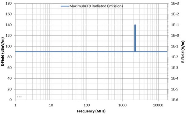
Figure 4-11: Falcon 9 worst-case radiated environment
Table 4-11: Falcon 9 worst-case radiated environment
| Frequency Range (MHz) | E Field Limit (dBμV/m) | Launch Vehicle Transmit System |
| 1.00 – 2200.0 | 90 | |
| 2200.0 – 2300.0 | 140 | S-band telemetry and video |
| 2300.0 – 18000.0 | 90 |

Figure 4-12: Falcon Heavy worst-case radiated environment
Table 4-12: Falcon Heavy worst-case radiated environment
| Frequency Range (MHz) | E Field Limit (dBμV/m) | Launch Vehicle Transmit System |
| 1.00 – 2200.0 | 90 | |
| 2200.0 – 2300.0 | 140 | S-band telemetry and video |
| 2300.0 – 2360.0 | 90 | |
| 2360.0 – 2395.0 | 140 | S-band telemetry and video |
| 2395.0 – 18000.0 | 90 |
4.3.6.3 MAXIMUM SPACECRAFT EMISSIONS
Maximum spacecraft emissions for Falcon 9 and Falcon Heavy are shown in Figure 4-13 and Table 4-13. Payloads should not emit radiation in
excess of the maximum allowable spacecraft emissions at any time during processing, integration or flight, as measured at the top of the payload attach fitting. Standard Falcon services do not permit active payload radiation during the countdown or
flight prior to separation from the second stage. This limit envelopes expected emissions as calculated at the plane between the payload attach fitting (PAF) and mission-specific payload adapter and includes EMI safety margin. Notch requests will
be assessed for compatibility on a mission-specific basis; notches for spacecraft transmitters can typically be accommodated to a level that is 6dB lower than SpaceX Avionics qualification limits. Please consult with SpaceX for your mission needs.
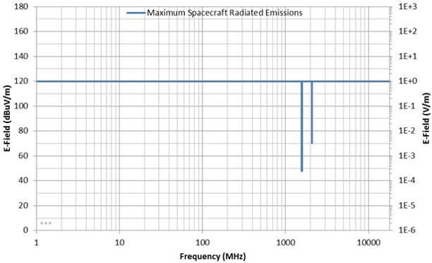
Figure 4-13: Maximum spacecraft emissions
Table 4-13: Maximum spacecraft emissions
| Frequency Range (MHz) | E Field Limit (dBμV/m) | Launch Vehicle Receive System |
| 1.0 – 1565.42 | 120.0 | |
| 1565.42 – 1585.42 | 48.0 | GPS L1 |
| 1585.42 – 2090.0 | 120.0 | |
| 2090.0 – 2093.0 | 70.0 | Stage 1 Telecommand |
| 2093.0 – 18000.0 | 120.0 |
4.3.6.4 FAIRING EMISSIONS ENVELOPE
Falcon launch vehicles have avionics inside the fairing. The fairing emission level is shown in Figure 4-14 and Table 4-14. This limit envelopes the maximum expected combined emissions from
these avionics, as calculated at the surface of the payload volume in Figure 5-1. EMI safety margin is not included.

Figure 4-14: Fairing avionics emissions envelope
Table 4-14: Fairing avionics emissions envelope
| Frequency Range (MHz) | E Field Limit (dBμV/m) |
| 30.0 – 18000.0 | 80 |
4.3.6.5 LAUNCH SITE EMISSIONS ENVELOPE
SpaceX has launch facilities on the East coast (SLC-40 and LC-39A) and on the West coast (SLC-4E). This limit envelopes the expected emissions at all SpaceX integration and launch facilities,
including Range sources, local radar systems, and communications systems in use at SpaceX facilities (WiFi, mobile phones, two-way radios, etc). Spacecraft designed and tested to this limit (plus appropriate safety margin) can expect to be compatible
with all known launch site emissions between spacecraft arrival and delivery to orbit. The envelope is calculated at the surface of the spacecraft and EMI safety margin is not included. Site-specific (not enveloped) analysis will be performed
on a mission-specific basis as needed to meet customer requirements. Notches for spacecraft receivers typically do not overlap with launch site emissions frequencies and can typically be accommodated.

Figure 4-15: Launch site emissions
Table 4-15: Launch site emissions
| Frequency Range (MHz) | E Field Limit (dBμV/m) |
| 100 – 400 | 132 |
| 400 – 1200 | 140 |
| 1200 – 1400 | 148 |
| 1400 – 11000 | 146 |
| 11000 – 18000 | 90 |
4.3.6.6 EMI SAFETY MARGIN
To account for unexpected variation in hardware and environments, 6dB of EMI safety margin is required. EMI safety margin is typically expected to be included on the “victim” side of the
source-victim analysis. Each emissions section in this guide specifies whether safety margin has been included in the envelope provided. When safety margin has not been included, it is expected that the relevant spacecraft susceptibility limit
will include 6dB of EMI safety margin.
4.3.6.7 LIGHTNING PROTECTION
SpaceX launch pads at CCAFS/KSC contain full lightning protection systems. The integration facilities and hangars are equipped with lightning grounding systems to protect personnel and hardware from
lightning. The SLC-40 and LC-39A launch pads are equipped with overhead wire lightning protection systems. These systems are designed to:
- Be a preferential path for lightning in order to prevent direct attachments to personnel and hardware in the protection zone.
- Avoid side flash between the overhead wires and flight hardware and ground systems.
- Minimize electromagnetic coupling to flight hardware and ground systems in order to protect sensitive electronics.
4.3.6.8 LIGHTNING RETEST
Well-defined lightning retest criteria are important to minimize both the risk of damage and the risk of missed launch opportunities for spacecraft and launch vehicles. As such, Falcon launch vehicles
have well-defined lightning retest criteria that are based on the lightning distance and amplitude data measured using Range-provided lightning monitoring systems. SpaceX requires spacecraft to provide lightning retest criteria based on lightning
strike distance and amplitude.
4.3.7 FAIRING INTERNAL PRESSURE
Inside the Falcon launch vehicle, the payload fairing internal pressure will decay at a rate no larger than 0.40 psi/sec (2.8 kPa/sec) from liftoff through immediately prior to fairing separation,
except for brief periods during flight, where the payload fairing internal pressure will decay at a rate no larger than 0.65 psi/sec (4.5 kPa/sec), for no more than 5 seconds.
4.3.8 PAYLOAD TEMPERATURE EXPOSURE DURING FLIGHT
The SpaceX payload fairing is a composite structure consisting of a 2.5 cm (1 in.) thick aluminum honeycomb core surrounded by carbon fiber face sheet plies. The emissivity of
the payload fairing is approximately 0.9. The fairing thermal insulation, which is attached to the outside of the fairing composite, is sized such that the composite never exceeds the ‘Bounding Fairing Composite Temperature’ profile
shown in Figure 4-16. The curve is truncated at 240 seconds, although the approximate time of payload fairing jettison for a geosynchronous transfer orbit mission from Cape Canaveral is typically earlier, at around 210 seconds into flight. Payload
fairing jettison timing is determined by customer requirements and physical limitations of the system.

Figure 4-16: Maximum payload fairing spot temperature seen by payload
4.3.9 FREE MOLECULAR HEATING
The payload fairing will nominally be deployed when free molecular aero-thermal heating is less than 1,135 W/m2. Other fairing deployment constraints can be accommodated as a standard service, although
they may modestly reduce vehicle performance. Please contact SpaceX regarding mission-unique fairing deployment requirements.
4.4 ENVIRONMENTAL COMPATIBILITY VERIFICATION
Prior to launch, SpaceX requires that customers verify the compatibility of their systems with the Falcon vehicles’ maximum expected flight environments. SpaceX initiates this
process by providing the applicable environments. The customer then summarizes its approach to environmental compatibility verification, and the process concludes with the customer providing test data to SpaceX, if necessary (Table 7-2).
Table 4-16 summarizes the typical verification activities performed by the customer and provides test levels based largely on Section 4.3 of this guide. Mission-unique limit levels and coupled loads analysis levels will be developed during the mission integration process and will serve as the basis for the verification activities. Alternate verification approaches may be acceptable, but coordination with SpaceX is required.
Table 4-16: Spacecraft environmental compatibility verification example
Environment | Verification Activities and Test Levels |
Quasi-Static Loads (Section 4.3.1) | Qualification: Limit levels x 1.25 Protoqualification: Limit levels x 1.25 |
Sine Vibration (Section 4.3.2) | Qualification: Limit levels x 1.25, two octave/minute sweep rate Protoqualification: Limit levels x 1.25, two octave/minute sweep rate |
Acoustic, Shock, and Random Vibration (Section 4.3.3 – | Customers shall provide details and justification showing compatibility of spacecraft hardware to acoustic, shock, and random vibration environments presented herein. SpaceX does not have specific requirements on spacecraft test margins; however, SpaceX generally recommends the following standards as references when developing spacecraft/component test campaigns: GEVS (GSFC-STD-7000), SMC-S-016, or NASA-STD-7001A. Test campaigns that do not align with methodologies presented in the above standards should have sufficient accompanying justification. SpaceX can aid in evaluation of these environments if requested |
Electromagnetic (Section 4.3.6) | SpaceX standard service includes an electromagnetic compatibility assessment. |
Pressure | SpaceX recommends venting analyses be conducted and may request insight into relevant analyses performed |
Thermal (Section 4.3.8) | SpaceX recommends thermal cycle and thermal vacuum testing be conducted and may request insight into relevant testing performed |